3D Cutter

Conception
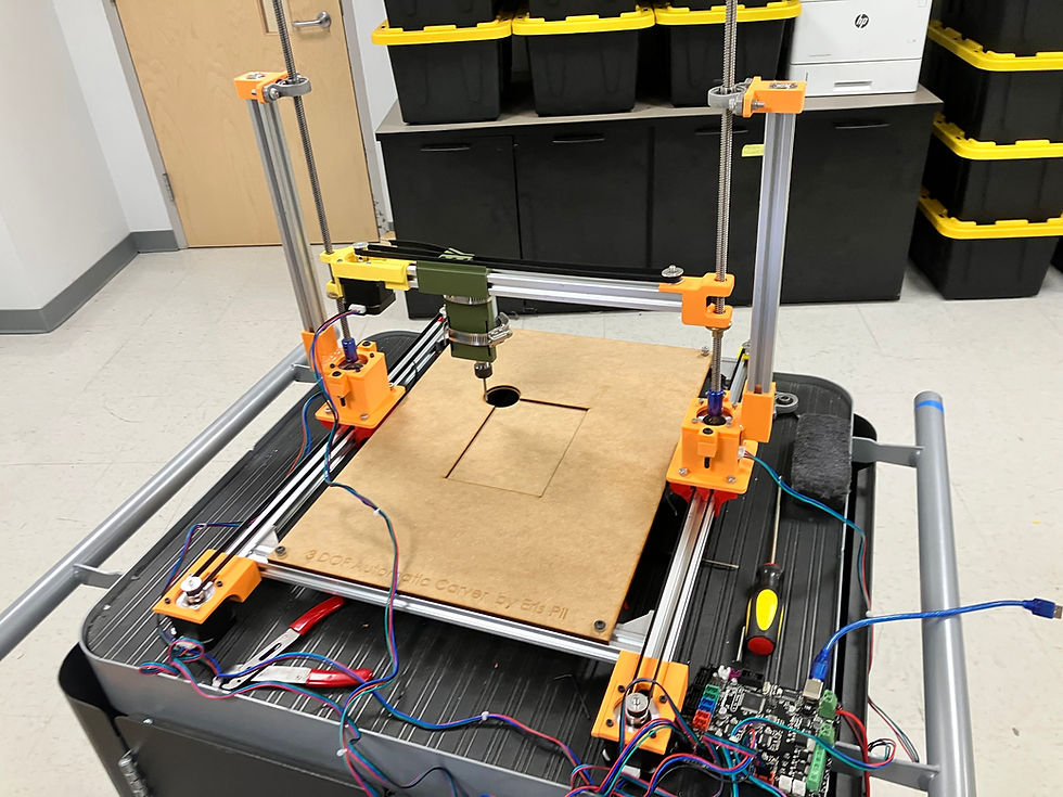
When I started this I intended it to be a week-long, prototyping project, exploring how CNC machines work. I had finished my 2D plotter project and initially conceptualized a simple 2.5 DOF cutter, specifically to help me with some artwork involving relief printing processes. As I worked on it, I revisited my initial ideas and expanded my designs to encompass a full motion system spanning 3 dimensions. This process challenged my skills regarding quick mechanical ideation and prototyping, precision and vibration reduction, circuitry design, coding, and calibration.

Prototyping and Physical Components
Designing the physical components of my design involved deciding how to construct and assemble the frame, motion systems, and selecting fasteners. The primary components for the frame were 80/20 20-2020 aluminum extrusions, held together by corner gussets and T-slots. The supporting frame for the z-axis system included similar aluminum extrusions slotted into a custom 3D printed support and fastened with a 1/4-20 screw into a tapped end. This aluminum extrusion had a self aligning bearing at the top fastened with screws, to ensure the z-axis lead screws remain aligned. I split the physical motion system into two different designs. For the x- and y-axes, I utilized GT2-6mm timing belts, to allow for for rapid, precise movement utilizing Nema-17 stepper motors. For the z-axis, I used the same type of stepper motors, but directed motion using lead screw nuts that secured the y-axis. The cutting spindle, a DC powered motor was secured with a worm-gear hose clamp to the y-axis slider.
Electronics and Code Control
I coded my own interpreter in C++ to convert G-code into physical motion (full documentation at the end of this page). This utilized the Arduino interface to upload the C++ code, and Repetier Host as the software to upload G-Code commands, which I ran on an MKS Base V1.6 board. As I worked through it, I added some additional features, such as homing to a preset position, rather than relying on limit switches because I didn't have enough. I also incorporated trapezoidal movement, feed rate control, arc interpolation, direction inversion, and motion control using Bresenham's line algorithm. I took a relatively simple approach to wiring, with an external DC power supply for the spindle and the stepper motors directly wired to the motor drivers on the MKS board. To conserve resources, I incorporated in my G-code a function to automatically turn off any components not in use after a minimum set time. I found that an ancillary benefit of this was reduced board overheating on longer runs.


Future Iterations
This is a super exciting space for me, and I am exploring some next refinements. These include:
-
Stability: Mounting the device and re-approaching my G-code to reduce vibration and chatter at high speed.
-
Flexibility: Designing new attachments that allow the machine to become a 3D printer or make cookie art.
-
Hardware/Software Improvements: Rewire spindle control to a motor driver attached to the MKS Base, to allow for M3, M4, and M5 G-code implementation.
-
Music! See button below.